Simulation Wheel Base
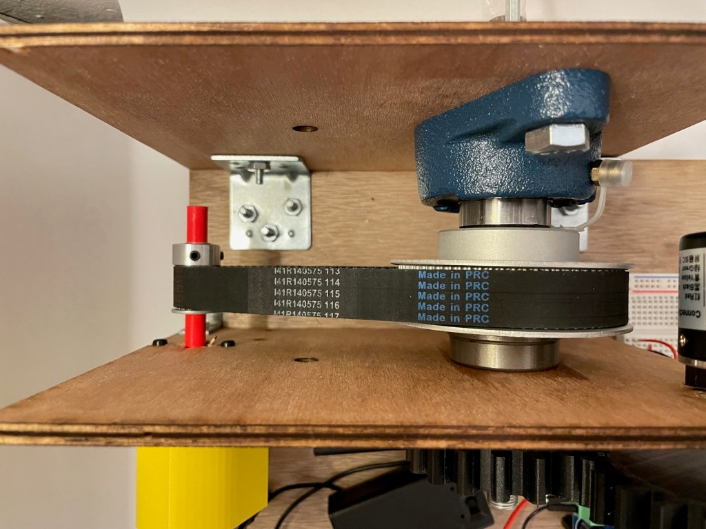
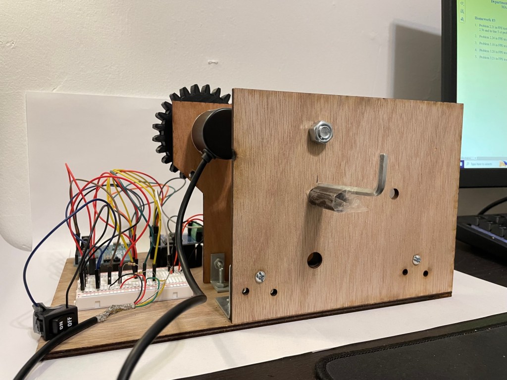
Draft Base for Testing
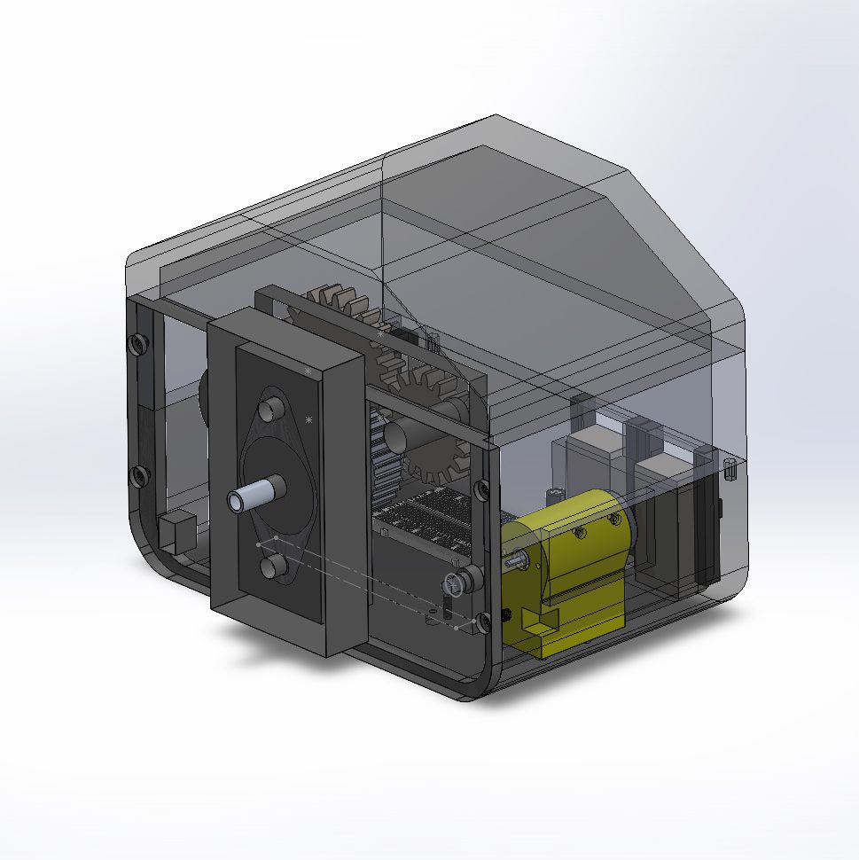
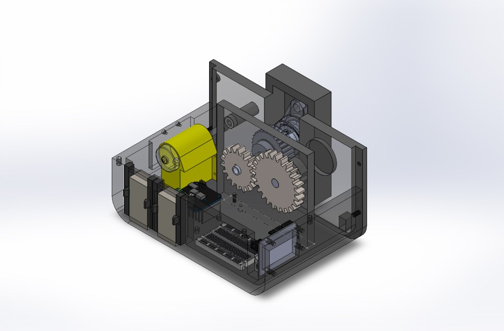
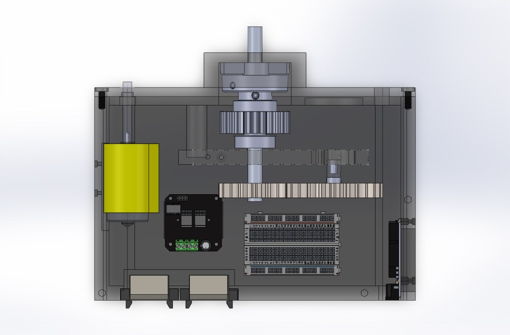
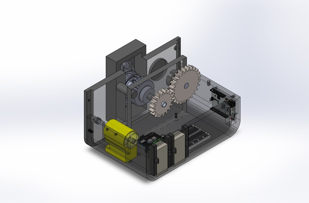
Final Case Design from SOLIDWORKS
Objectives
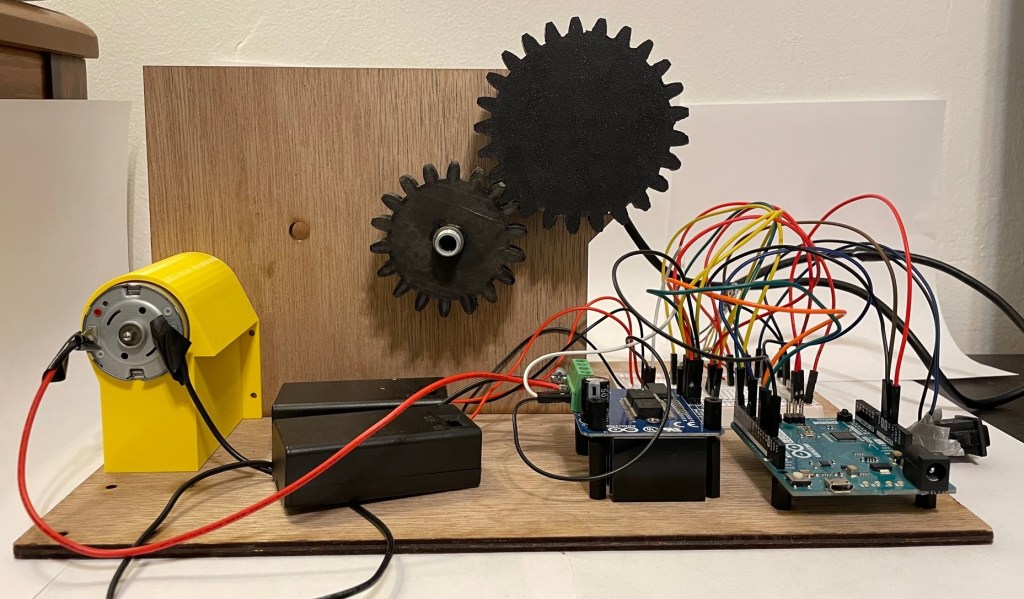
- Confirm the individual components worked
- Manufacture and design a draft base to test system and set positional requirements
- 3D print support parts and mechanical components for system functionality
- Wire the electrical system together and test system controls
- Design and print a final design to hold components to a commercial standard
The Idea
I was inspired to take on the challenge of creating a simulation racing wheel to enhance the driving experience in racing games. Looking at simulation racing wheels to buy, there are cheaper wheels that only offer a basic input control and then there are more expensive systems that include force feedback in the wheel including other sophisticated configurations. Since the range in prices and complexity of the wheel were very different in both fields, I decided that I would make a middle-ground wheel and learn from the process of creating a system of this type from scratch.
Intro
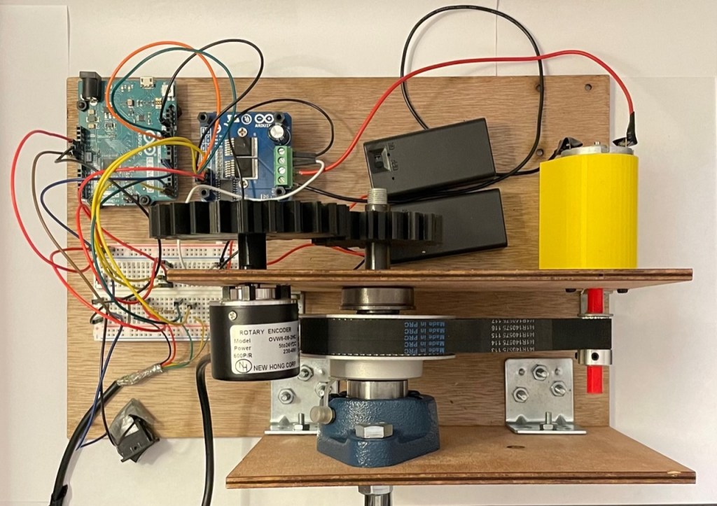
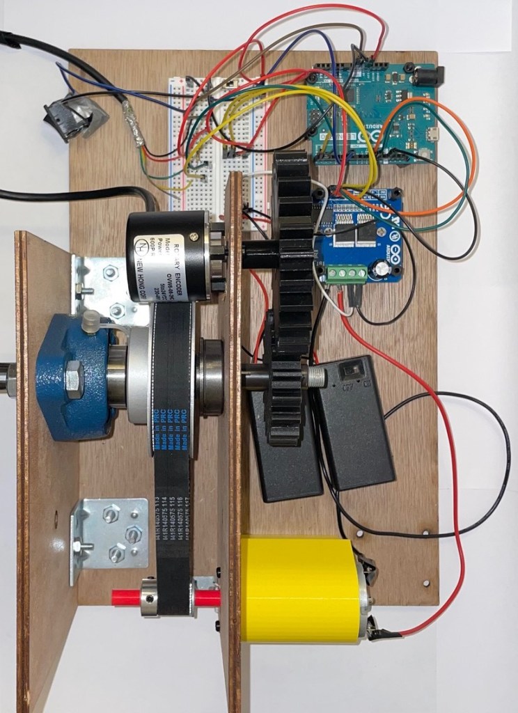
I had bought some components before seriously taking on this project, which I will talk about later as the amateur mistakes I made, and had an idea of how the system would work. Using forum’s and videos of other people’s projects, I found that the actual wheel and wheel base are considered different components of the racing controller as a whole. For this section, the focus is on the wheel base. The wheel base is the system that gives the actual wheel it’s function. It is composed of an input for steering in game, a shaft that connects the steering wheel to the wheel base, a motor which works for the force feedback mechanism, and a belt and pulley system to link the force feedback system to the shaft. These individual functions are supported with the use of electronic components that are explain in detail in this report.
More details coming soon…